
Gear Metering Pumps & Meter Mix Dispense Machines with highest accuracy for processing liquids and pastes.
High-precision rotary stroke bearings for backlash-free linear and rotational movements for use in machine and device construction.


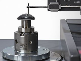


Experience the latest products in measurement technology, from digital calipers to fully automated inline solutions ✓newest features ✓highest quality


As an internationally active company, Mahr holds its patents not only in Germany, but worldwide.


Mahrの革新的な測定工具:アナログモデルからワイヤレス伝送機能を内蔵したデジタルモデルまで、多様なノギス・マイクロメータ・ダイヤルインジケータ。Mahrの比較測定器と基準器は、製造における高精度の測定に不可欠です。

アナログからデジタルまで、ノギスの全領域を網羅。簡単な操作、ワイヤレス、高精度。製造現場での効率的な使用に最適です。

安心できる読み取やすいデジタル表示、モダンなデザイン、そしてMahrのいつもの正確さが特徴のデジタルキャリパー。製品レンジには、すべてのアプリケーションに対応するための計測器が揃っています。データ通信用の各種インタフェースとIP67までの保護等級により、満たさない要求はありません。

グレアのない読み取り、硬化鋼、盛り上がったガイドウェイがスケールを保護し、最高の精度をもたらします。Mahrの高品質キャリパーの機能にクラシックなアナログノギス/デプスゲージを装備。

大型でハイコントラストのダイヤルと耐衝撃測定ツールにより、精度が持続します。高速で安全な読み取りのために、試行錯誤を重ねた機械設計を採用。

多彩な設計で最高の精度を実現。Mahrのマイクロメータには伝統的な機械式タイプ、デジタルタイプ、ワイヤレスタイプがあります。

クリアなデジタルディスプレイ、モダンなデザイン、いつものMahrの精度が、このデジタル外部マイクロメータを特徴づけています。製品レンジには、すべてのアプリケーションに対応するための計測器が揃っています。データ転送のための様々なインタフェースとIP65までの高い保護等級により、満たせない要求はありません。

アンチグレア読み取り、断熱プレート、精密研磨されたスピンドルによる最高の精度。Mahrの高品質マイクロメータの機能。

連続する部品(シャフト、ボルト、シャンク)の信頼性の高い高速検査に特に適しています。寸法精度が高いことで知られており、ダイヤルコンパレータで一目で読み取れます。
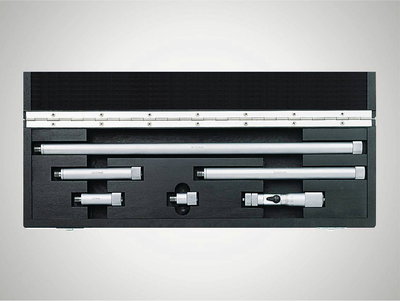
2,500mmまでの大口径の測定や距離の試験に適しています

目盛板またはデジタル表示、あるいはピストル型グリップを持ったクイック測定器として利用できます。Mahr3点式内側マイクロメータは、自動セルフセンタリングにより常に信頼性の高い測定結果を提供します。

アンチグレア読み取り、精密研磨されたスピンドルによる最高の精度。Mahrの高品質マイクロメータの機能。

アナログからデジタルまでの、ダイヤルゲージ、ダイヤルコンパレータ、ダイヤルテストインジケータの全範囲。簡単な操作、ワイヤレス(オプション)、高精度。製造現場での効率的な使用に最適です。

クリアなデジタル表示、堅牢な構造、高いMahr精度を特徴とするデジタルダイヤルゲージです。製品レンジには、すべてのアプリケーションに対応するための計測器が揃っています。データ転送のための様々なインタフェースとIP54までの高い保護等級により、満たさない要求はありません。

高感度と高精度の理由:測定ツール軸のしっかりした取り付け、精密に噛み合わされたホイールとピニオン、精密に取り付けられた測定ピン。

高感度と高精度の理由:測定ツール軸のしっかりした取り付け、精密に噛み合わされたホイールとピニオン、精密に取り付けられた測定ピン

Millimessダイヤルコンパレータは、アナログのダイヤルゲージと比較して、さらに精密な部品を使用しているため、測定精度が高く、ヒステリシス誤差が大幅に向上しています。これらの利点は、特に振れ試験、真直度や平坦度測定、比較測定において顕著に現れます。

高精度の誘導型Millimessダイヤルコンパレータは、0.2μmまでのデジタルインクリメントが可能です。公差モニタリング、動的測定の最小または最大記録、数値と目盛りの併用表示、簡単なデータ転送などのユーザーフレンドリーな操作機能により、精密測定に欠かせない高精度測定器です。

コンピュータに最適化された高感度の測定ツールにより、最高の信頼性と精度が保証されます。作業場でのラフな使用に備えて、ディスプレイは硬化ミネラルガラス板によって傷や破損から見事に保護されており、さらにシーリングが液体の浸透を確実に防ぎます。

読み取りやすいデジタル表示、堅牢な設計、Mahrの高い精度が特徴のデジタルダイヤルテストインジケータです。

NC機械、マシニングセンタおよび放電加工機用のMahr 3D測定プローブは、セットアップとダウンタイムを短縮します。ワークピースやフィクスチャの基準エッジへの正確な接触に最適です。

統合型ワイヤレス、外部ワイヤレスモジュール、USB、Opto RS232、またはDigimaticのいずれかによる:使用するインタフェース規格に関わらず、MarConnectは常に最適な接続を提供します。

多くのMahr精密ゲージには、MarConnectインタフェースを装備したデータ出力があります。使用するインタフェース規格(USB、Opto RS232、またはDigimatic)に関わらず、MarConnectは常に最適な接続を提供します。

Mahrのワイヤレス製品レンジは、完全な移動性とともに正確な測定結果を保証します。最新の簡単な測定方法 – 有線技術の制約なし。

MarStandの測定用三脚、測定台、ラジアル振れゲージは、高精度な測定結果の基礎となる高い安定性を提供します。また、ダイヤルインジケーター、ダイヤルコンパレータ、ダイヤルテストインジケータ測定器や測定プローブに必要なサポートを提供します。
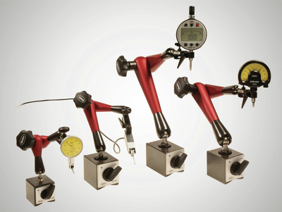
測定用三脚は、安定したデザインにより、正確な測定結果の基礎を提供します。また、ダイヤルインジケーター、ダイヤルコンパレータ、ダイヤルテストインジケータ測定器や測定プローブに必要なサポートを提供します。
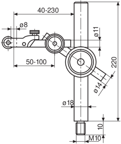
MarStandのポストとサポートアセンブリは、個々のソリューションに使用されており、正確な測定結果の基礎となる高い安定性を提供しています。また、ダイヤルインジケーター、指針測微器(コンパレータ)、ダイヤルテストインジケーター測定装置と測定プローブのために必要なサポートを提供します。

測定テーブルは、精密で水平なテーブル、安定した測定コラム、強いアーム部品を組み合わせたものです。MarStandの測定テーブルは、極めて安定したデザインにより、正確な測定結果の基礎を提供します。

半径方向振れゲージは、生産現場に近い環境でシャフトの位置および形状誤差を検出する最も簡単な方法です。堅牢なMarStand半径方向振れゲージは、豊富なモデルにより、幅広いワークピース要件と正確な測定結果の基礎を形成します。
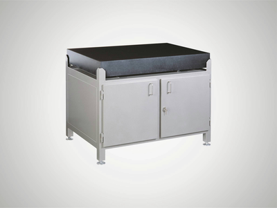
硬質御影石製のテストプレートは、高い強度と寸法の安定性により、高さ測定器の表面として最適です。

指示ゲージを比較ゲージとして使用すれば、製造現場での正確な測定に最適なツールとなります。ゲージを基準器としてセットすることにより、偏差マージンを減らし、温度変化による測定結果への影響を最小限に抑えることができます。

指示スナップゲージはシャフト・ボルト・シャンクなどの円筒形状部品の精密測定に最適な測定ツールで、特に連続して製造された部品を安全かつ迅速にテストするのに適しています。寸法精度はダイヤルコンパレータで指示され一目で読み取ることができます。

内径測定器は、穴の直径、真円度、円錐度を正確に測定するのに最適なツールです。

当社の隙間ゲージは、各種フィルム、シート、プレートを特に高速に測定するための堅牢でシンプルな製品レンジを提供します。

キャリパーや内径マイクロメータネジなどの一般的な測定器がワークの形状が原因で使用できない場合に、キャリパーゲージは完璧なソリューションになります。
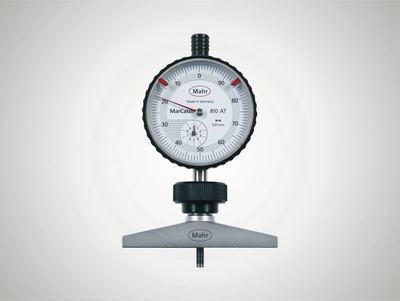
当社のデプスゲージは、特に高速な深さ測定のために堅牢でシンプルな製品レンジを提供しています。8mm取り付けシャフトにより、測定タスクに応じてダイヤルゲージ、ダイヤルコンパレータ、およびプローブを使用できます。

ユニバーサル計測器は、基準器との比較測定により、温度変動が測定結果に与える影響を最小限に抑えることができるため、生産現場での精密測定に最適なパートナーとなります。

ギヤ、ねじ、テーパー、くぼみのいずれであっても:Multimar万能測定器は、標準的な測定器では適さない、ほとんどすべての内部および外部測定に最適的なソリューションです。ベーシックユニットの選択が可能で、幅広いアクセサリーをご利用いただけます。

内側および外側測定器を正確に調整。844 Sセッティング機器を使用すれば、大きな寸法の場合でも、すべての測定タスクに完全に対応できます。

肩、狭いカラー、くぼみのいずれのセンタリングでも:Multimar 36Bユニバーサル測定器は、ほとんどすべての内径および外径測定に理想的なソリューションです。ベーシックユニットの選択が可能で、幅広いアクセサリーをご利用いただけます。

信頼のMahrセッティング基準片とゲージ - 正確な測定結果の基礎となるため。

信頼のMahrセッティング標準片 - 正確な測定結果の基礎となるため。

Mahrゲージブロックでは、高品質のリファレンス用と作業用の標準器を自由に使用できます。4つの公差等級と2つの素材から、作業場、生産、品質保証の要件に合わせて選ぶことができます。

Mahrのピンゲージは、3つの公差クラスと様々な設計のものをご用意しています。作業場、生産、品質保証の要件に合わせて選ぶことができます。

電気式測長器の要件は、その用途と同じくらいさまざまです。優れた信頼性、精度、そして簡単な操作が求められます。
電気式測長器の要件は、その用途と同じくらいさまざまです。優れた信頼性、精度、そして簡単な操作が求められます。Millimarコンパクトなコラム測定器はこれらの要件を満たしています。
Millimar長さ測定器は、コンパクトで堅牢、そして使いやすい測定器です。生産現場や測定室での複雑な測定作業を可能にする、汎用性の高い評価・指示装置です。

モジュールとソフトウェアの多様な組み合わせの選択肢により、これまで以上に作業環境やツールを個別に設計する機会が得られます。
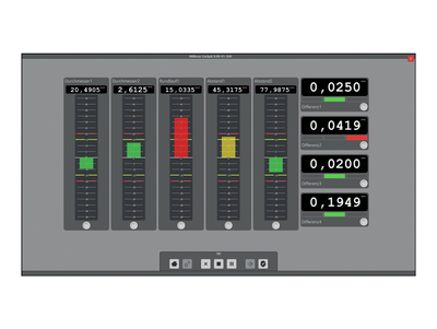
Smart and universally applicable software for complex measurement tasks in the manufacturing sector

Millimar トランスデューサーは、計測チェーンにおいて最も重要なコンポーネントです。その特性で測定全体の品質が決まります。用途に応じて、さまざまな技術をご利用いただけます。例えば、Millimarの誘導測定プローブなど。これらの製品は、頑丈で用途が広く説得力のある価格です。

厚さ測定、半径方向の振れ、同心度のどれであっても:誘導プローブにより、形状、サポート、または半径方向の振れの偏差に関係なく、測定値と偏差を記録できます。大きな利点は、直線性の範囲が広く、干渉の影響を比較的受けにくいことです。プローブは主に生産現場での比較測定に使用されますが、センサーの具体的なタスクは様々です。
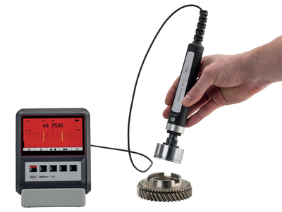
ボアプラグゲージは、ボアの直径、真円度、テーパーを迅速に検査するために特に適しています。他の内部測定器のように反転点を探す必要がないため、特にデジタル指示計との併用や測定値のさらなる処理に適しています。

空気圧長さ測定器は、高精度と長期的な安定性が特徴です。測定ノズルによる非接触測定は、ワークに損傷を与えません。未洗浄の、油や潤滑剤が付着した、またはラップでコーティングされたワークでも
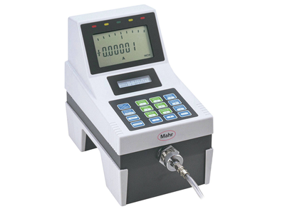
Millimar長さ測定器は、コンパクトで堅牢、そして使いやすい。生産エリアでの測定タスクの複雑さを管理できる用途が広い表示・評価装置です。

測定結果は101個の3色LEDで表示され、離れた場所からでも簡単に読み取ることができます。プログラム可能な警告および許容限度を超えると、セグメントの色が緑から黄色または赤に変わります。

Millimar空気圧式測定器は寸法の偏差を迅速かつ正確に記録します。これは、産業の生産現場や測定室で長年にわたり能力を発揮しています。

外出先での測定と評価に。
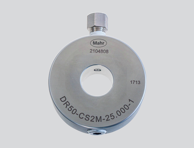
空気圧測定リングを使用した非接触測定により、ワークへのダメージがない。

エア測定技術のアクセサリーを使用して、測定ステーションを測定タスクに適合させます。

信頼のMahrセッティング標準片 - 正確な測定結果の基礎となるため

空気圧式測定器(ノズルリングゲージ)の設定 焼入れ、エージング、研磨、ラップを入念に実施。

空気圧測定器(ノズルプラグゲージ)の設定 焼入れ、エージング、研磨、ラップを入念に実施。

電子水準器は、高速応答、高分解能、優れた再現性があります。
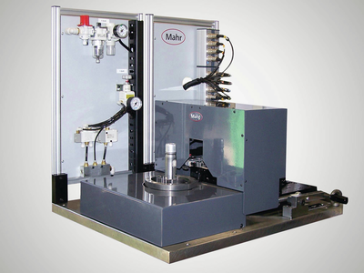
標準的なソリューションではもう十分ではないとき。個別カスタマイズソリューション

測定に高い目標を設定したいですか?Digimarがそれに応えます!

作業現場でのワークのスクライビングやマーキングに。高さや距離の測定が簡単に。
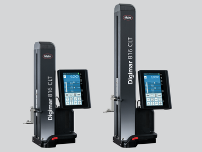
Touch operation, ergonomic handling and a wide range of evaluation options: This is what the Digimar 816 CLT height measuring device stands for.
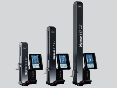
タッチ操作、人間工学に基づく操作性、幅広い評価オプション:これが、Digimar 817 CLT高さ測定機の特長です。

精密長さ計測は、絶対測定と相対測定の両方を対象とした高精度の寸法計測を代表します。
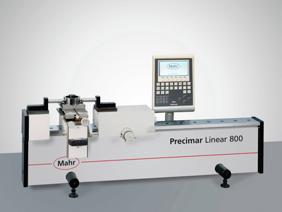
作業現場向けの万能で使いやすい長さ測定および設定装置
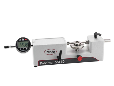
作業現場向けの万能で使いやすい長さ測定および設定装置

シンプルなゲージブロックテストスタンド、全自動ダイヤルゲージテストスタンド、ULMデバイスから、超精密で部分的に自動化されたCiMユニバーサル測定機まで、幅広い製品範囲により、Mahrは常に、生産、測定室、および 校正ラボに実用的なソリューションを提供しています。つまり、効率性の高い測定プロセスにより最大限の精度を実現します。

クラシックなULMでも、電動のPLMやCiMの機器でも。Mahr汎用長さ測定機は、ユーザーフレンドリーで高速、かつ信頼性の高い測定を、最小限の不確かさで実現します。

ダイヤルインジケータ、ダイヤルテストインジケータ測定装置、ダイヤルコンパレータ、およびプローブの半自動および全自動試験 - 効率的で正確。

ダイヤルインジケータ、ダイヤルテストインジケータ測定装置、ダイヤルコンパレータ、およびプローブの半自動および全自動試験 - 効率的で正確。

ダイヤルゲージ・テストインジケータ・コンパレータの手動テスト - 簡単で正確

信頼のMahrゲージブロックコンパレータ - 標準片の正確な試験の基礎となるため

顕微鏡は、距離、半径、角度を素早く検査するために、ほとんどすべての産業で使用されています。ラボや生産現場の近くで。

明るくシャープな立体画像を実現する高品質レンズを採用したステレオズーム顕微鏡。デジタルカメラの追加使用に対応した双眼または三眼。

顕微鏡は、距離、半径、角度を素早く検査するために、ほとんどすべての産業で使用されています。ラボや生産現場の近くで。

産業用および研究用の表面計測

公差の厳しい構造化された機能表面には、ワークや対象物の形状を短時間で記録する高精度な測定システムが必要です。

輪郭計測技術により、大まかな形状のズレを把握することができます。


光学式測定器による正確な輪郭測定

輪郭測定と粗さ測定の組み合わせ:プロフェッショナルオールラウンダー
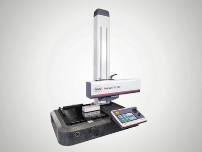
輪郭測定と粗さ測定の組み合わせ:プロフェッショナルオールラウンダー

ISO 25178 / ISO 4287に準拠した2D/3D輪郭測定および粗さ測定

産業用および研究用の3D表面計測

モバイル測定器でどこでも測定!
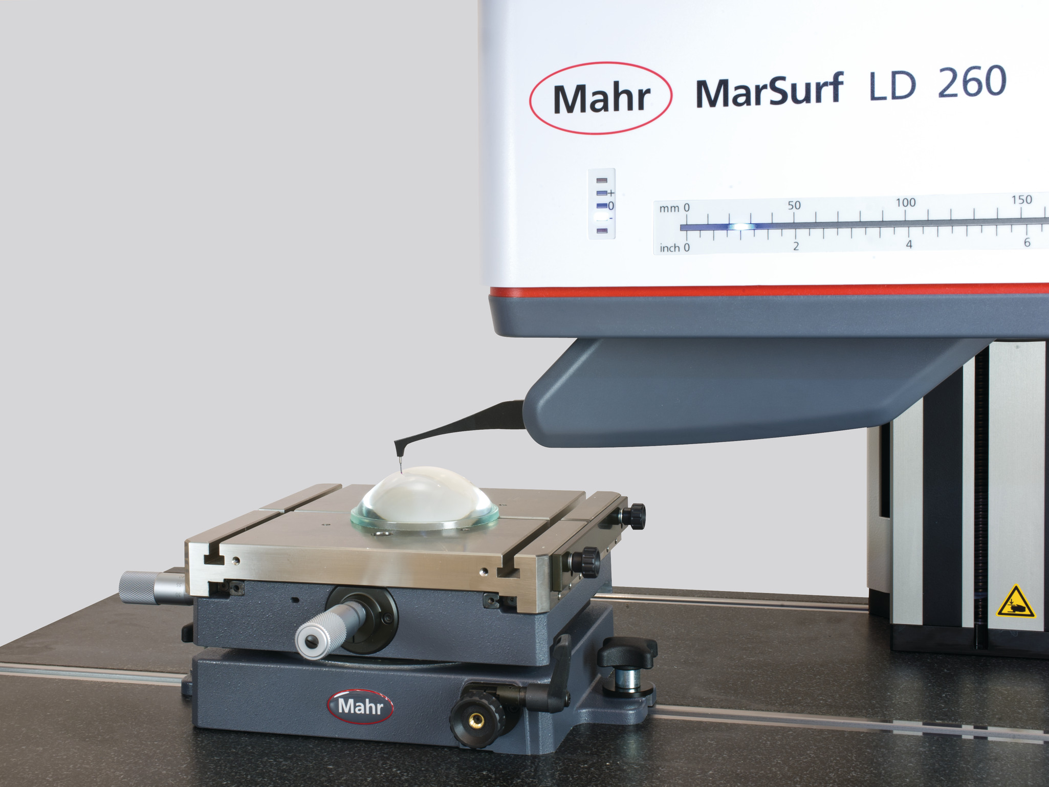
高精度レンズ用測定ステーション

標準的なソリューションではもう十分ではないとき。個別カスタマイズソリューション

公差の厳しい構造化された機能表面には、ワークや対象物の形状を短時間で記録する高精度な測定システムが必要です。
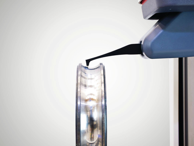
測定室やラボでの汎用性とパワフルな性能
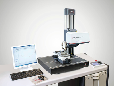


輪郭測定と粗さ測定の組み合わせ:プロフェッショナルオールラウンダー

輪郭と粗さ測定用触覚測定ステーション

2D/3D 輪郭および粗さ測定、ISO 25178 / ISO 4287 準拠

産業用および研究用の3D表面計測

モバイル測定器でどこでも測定!
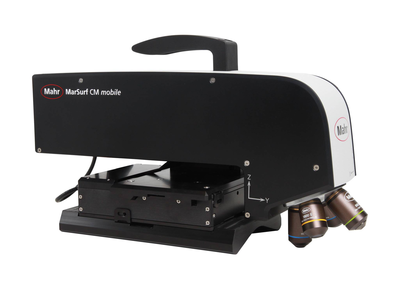
モバイル3D表面測定
製造現場での使用

モバイル測定器なら、測定結果が必要なまさにその場所を測定できます。

超高精度レンズ用測定ステーション

標準的なソリューションではもう十分ではないとき。個別カスタマイズソリューション
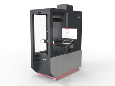
Metrology
Experience outstanding features combined with extreme flexibility in workpiece size and increase your productivity in the production environment.
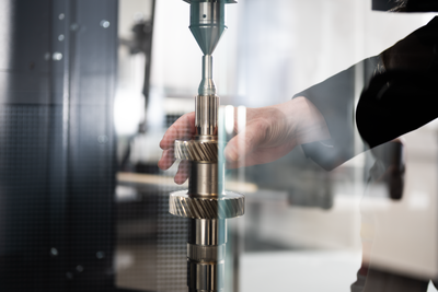
Flexible measurement of workpieces that can be clamped between centers
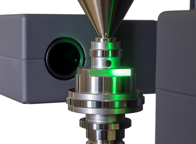
High resolution and very fast matrix camera for measuring a large number of features on rotationally symmetrical workpieces.

Fast optical matrix camera in combination with high-precision touch probes for measuring a large number of features on rotationally symmetrical workpieces.
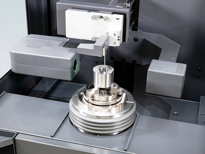
Flexible clamping options and high-precision alignment using a fully automatic centering and tilting table

High resolution and very fast optical matrix camera for measuring a wide range of rotationally symmetrical workpieces. Addition of a fully automatic centering and tilting table for extremely fast, mechanical alignment and flexible clamping options.

Fast optical matrix camera in combination with high-precision touch probes for measuring a large number of features on rotationally symmetrical workpieces. Addition of a fully automatic centering and tilting table for extremely fast, mechanical alignment, flexible clamping options and, for example, internal measurements.

真円度、平面度、真直度、同軸度など、形状や位置の公差を検査するシステム、およびその他の測定タスク。手動から全自動まで。
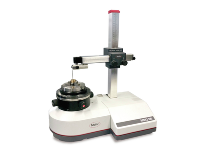
この装置は、真円度、真直度、同心度などの特徴を、簡単に、コスト効率良く、しかも高精度に測定します。 当社の手動形状測定器は、測定室と生産現場近くでの測定の両方に適しています。
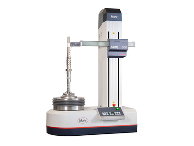
当社の自動形状測定システムは、最高レベルの自動化、柔軟性、精度を備えた安定した革新的な装置により、検査コストを押し上げることなく、プロセスコストを削減します。

Metrology
Experience outstanding features combined with extreme flexibility in workpiece size and increase your productivity in the production environment.
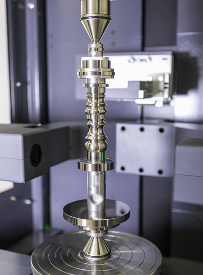
Flexible measurement of workpieces that can be clamped between centers

Flexible clamping options and high-precision alignment using a fully automatic centering and tilting table

過酷な製造環境で 使用 される光学式および触覚式シャフト測定システム。 一般的な回転対称のワークの完全測定が可能です。

過酷な作業場環境で使用するための、ユニバーサルで完全自動の堅牢な光学シャフト測定機です。
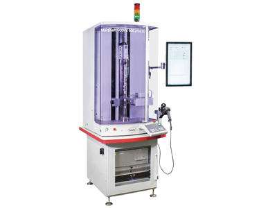
過酷な製造環境で 使用 される光学式および触覚式シャフト測定システム。 一般的な回転対称のワークの完全測定が可能です。

Metrology
Experience outstanding features combined with extreme flexibility in workpiece size and increase your productivity in the production environment.

Flexible measurement of workpieces that can be clamped between centers

Flexible clamping options and high-precision alignment using a fully automatic centering and tilting table
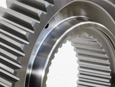
高度に専門化されたギア分析から完全に統合された連続測定まで、Mahrは、最新のギアおよびギアボックス製造のあらゆるレベルで信頼できるパートナーです。
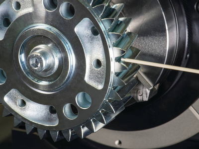
製品の生産現場での計測と製造プロセスへの迅速なフィードバックにより、廃棄品を防ぎます。


表面や形状を高速かつ非接触で記録するための幅広い技術や製品。

顕微鏡は、距離、半径、角度を素早く検査するために、ほとんどすべての産業で使用されています。ラボや生産現場の近くで。

粗さ、輪郭および他の多くの表面パラメータの決定。

産業用および研究用の表面計測

ナノメートル精度の微小な粗さ

地形表面と形状の光学的解析

定評あるMahrの品質で再生されたシステム

Touch operation, ergonomic handling and a wide range of evaluation options: This is what the Digimar 816 CLT height measuring device stands for.
Using Air Gaging for Measurement of Orthopedic Devices
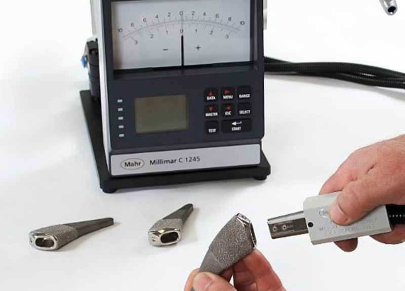
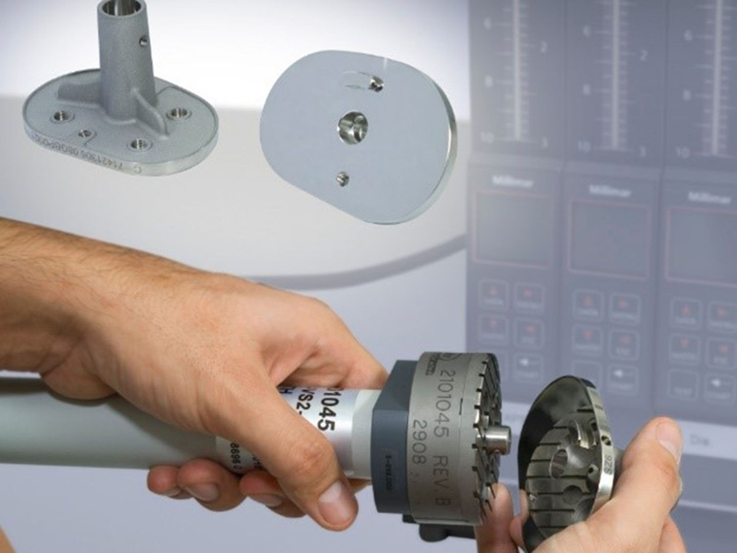
Precision orthopedic components can only meet the necessary high-quality standards when the individual manufacturing steps (starting with cutting and ending with final machining) are consistently stable. This requires process-oriented inspection of characteristics, rapid feedback when tolerances have been exceeded, and documentation of all process data.
Typically, as parts move through the manufacturing process from raw material to final product, dimensional tolerance, surface finish, and geometric characteristics become more critical. One of the dimensional characteristics that is measured at the end of the orthopedic device manufacturing process is the tight tolerance on the tapers used to match the parts together. For example, most hip and knee implants use tapers to provide optimal alignment and to “lock” the components into position. During the manufacturing of these devices, control of both taper and size determines how well the orthopedic implants will perform over their lifetime.
Why Air Gaging is the Most Effective Method
As tolerances become tighter, gages must be more robust, have the right design characteristics to fixture the parts properly, and have the proper resolution and accuracy to measure the required tolerances. Increasingly, air gaging has become the inspection tool of choice for controlling these critical parameters. Air gaging is extremely precise and provides very high resolution. It is typically used for applications where the tolerance is fairly tight — usually less than ±0.001 in. — and surface roughness is less than 50 µin. Ra. When these conditions exist, as with precision medical tapers, air gaging is often the best solution for the application.
Air gaging is also particularly well suited to checking dimensional relationships. Furthermore, air gages are fast, easy to use, and can last for years — measuring millions of parts — under the toughest shop conditions. Air gaging can even be used in some cases to inspect and estimate certain form features on a part.
The air jet, the small orifice that emits air to begin the physical process of creating a gage, is the reason that air gaging is so useful for measurement of orthopedic tapers. No other gaging sensors are as small or can be placed in such close proximity when measuring multiple diameters or geometric forms. Small electronic sensors or eddy current type sensors may approach the size of an air jet, but nothing can match their economy or ability to work in a shop environment at the point of manufacture.
It is possible to measure diameter and taper with either a combination of electronic sensors or coordinate measuring machines (CMMs) with touch probes. However, the air jet can be built in a precision tool that can be used to measure the part at the point of manufacture. This can be done in one fast measurement with very little operator involvement. Neither CMMs nor optical gaging have the speed and the precision required to measure 100 percent of parts on the shop floor while providing immediate feedback on the performance of the process.
Selecting the Right Gage Design
Just as there are many manufacturers of taper components, there are many methods for specifying taper requirements. The reference face may be different between manufacturers and tolerances can be specified in different ways.
Depending on how the assembly goes together, tolerances may be tighter on the taper than on the diameters, or vice versa. Alternatively, there may be a combination of taper tolerances on only one diameter. Thus, the specification on the print is the best guide in choosing which air taper gage design to use. With air gaging, the tooling is made specifically for each different taper application, so it is critical to properly understand the requirements.
Even so, the flexibility and benefits are hard to beat. Air gaging provides very high resolution and uses a sensor that is 0.050 in. or smaller; sensors can be placed within 0.10 in. of each other and can be combined to produce any number of dimensional and geometric results right on the shop floor.
Types of Air Taper Gages
Medical implants must be extremely durable and able to withstand a lot, so the taper fit between the female and male components is critical. The two pieces have to lock together and sit at the correct height. During manufacture, it is common to inspect 100 percent of parts to ensure the accuracy of both components. This is usually done with differential air gaging, which combines the necessary high resolution and accuracy with the speed, ease of use, and ruggedness required on the shop floor.
The most common type of air gage taper tooling has two pairs of jets on opposing air circuits and is designed for a “jam fit” between the part and the tool (see Figure 1). If the rate of taper is too great, there will be excessive clearance between the two surfaces at the small end of the taper. If the rate of taper is too small, there will be excessive clearance at the large end.
Either situation can reduce the rigidity of the connection, which over time can cause the “lock” to fail by becoming loose and/or rotating. If the taper angle is correct but the size is incorrect, then the overall length of the orthopedic assembly will be incorrect and provide unexpected results after implant.
Jam-fit tooling does not measure part diameters. Rather, it displays the diametrical difference at two points on the workpiece, as compared to the same two points on the master. If the difference in diameter at the large end of the taper is greater than the difference in diameter at the small end, the upper jets will see more back pressure than the lower jets. This will reflect negative taper, or a larger taper angle. If the diameter difference at the small end is greater, the reverse is the case and the gage will read positive taper.
However, because a differential air meter displays diametrical differences only, it will not display the part’s diameter at either location. So, while this type of air tooling provides a good indication of taper wear and allows a loss of rigidity in the connection, to be predicted it does not tell anything about the taper components’ positioning accuracy.
For that, a clearance-style (sometimes referred to as a shoulder style) air tool is needed in which an air taper ring cavity is sized to accept the entire taper part. Depending on where the part’s reference surface is, the part can be referenced on the end of the taper or on a flange (shoulder) against the top surface of the part. This makes it possible to measure diameters at known heights (in addition to the change in clearance, as with the jam-fit type). An additional set of jets may be added to inspect for bell-mouth and barrel-shape, two more conditions that reduce the contact area between the male and female components.
The third type of air taper gage is a cross between the aforementioned styles. This is called a simultaneous fit taper gage. It is essentially a jam-fit air tool with an indicator that references on the face of the datum surface. This indicates how far the air tool goes into the part being measured.
So, while the air gage provides a reading of the taper angle, the indicator provides an indication of the size of the diameters. When measuring a female taper part, if the taper diameter is too large, the gage will go farther into the part. If the diameter is too small, it will not drop into the part as far as expected.
Accounting for Surface
Because air gaging is so precise and high resolution, it can be influenced by the surface finish of the part. Some parts have designer surface finishes that would normally not be conducive to air gaging. For example, measurements of a prosthetic femoral stem include the roughness of the polished area found on the proximal portion of the stem. This area is subject to close visual inspection for asperities by the orthopedic surgeon. To verify surface and waviness quality of the taper, a contour gage is used to trace the taper in the same measurement.
This causes complications for the application of air gaging as a good surface is necessary to utilize it. During normal use, the air jet’s curtain of air covers an area on the surface of the part. This air curtain is restricted by the surface to create the back pressure, which is required to do the measuring. On a smooth surface, the difference between the average surface and the peaks, which in the case of an ID part means minimal clearance, is fairly insignificant. But if the surface is very rough, the area, or the point at which the back pressure is built up, can be significantly different. This can register on the air gage display and affect the indicated diameter.
However, when there are surface finish issues special steps can be taken to account for them. As long as the surface finish is less than 50 microinches, the offset can normally be ignored. Even if it is not, if the effect is discovered during process development, the error can be compensated for and the effective diameter shown to the machine operator. By understanding the nature of the surface and how it reacts to the open-air jets, electronic amplifiers and gaging computers can also provide excellent calculations of average or maximum diameters.
Conclusion
Precision orthopedic components must consistently meet extremely high-quality standards. One of the critical dimensional characteristics that is measured during the orthopedic device manufacturing process is the tight tolerance on the tapers used to match the parts together. As tolerances become tighter, gages must be more robust, have the right design characteristics to fixture the parts properly, and have the proper resolution and accuracy to measure the required tolerances. Increasingly, air gaging has become the inspection tool of choice for controlling these critical parameters.
This article was written by George Schuetz, Director, Precision Gages at Mahr Inc., Providence, RI.
